
Step -by -step guide: Using Solidworks to Bring the Fibonacci Pattern to Life in Your Product Designs

Nature has been the ultimate problem solver for over 4 billion years and its beauty never ceases to amaze and I am fascinated by its beauty.
As designers, we have much to learn and get inspired from. For instance, the sunflower found its way to optimize the production of its offspring. It efficiently packs the maximum seeds it possibly can in a given area which generates a beautiful geometrical figure. At first sight, the pattern seems symmetrical but is not. It has its randomness that makes each single sunflower unique. I like the magic of it.
I wanted to reproduce this exact pattern for an IoT project for the startup Monitorlinq. I have been struggling to create it using Solidworks but I managed to make my way through it. Here is how I got there, and so can you.
Step 1: Understanding the Mathematics of Nature

The mathematical equation is the sunflower seed is as follow:
r = c.√n
θ = n.γ
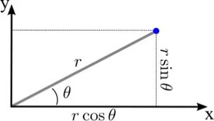
Where:
r and θ are the coordinates of a point in a polar plane;
n is an index;
c is a constant scaling factor
γ is the angle between a new seed and its closest neighbor.
We now want to convert polar coordinates into cartesian coordinates.
x = r.cos(θ)
y = r.sin (θ)
And convert the degrees into radians
θ(deg) = θ(rad).(180/π)
Optimal figure:
2.618 θ ≈ 360˚
θ ≈ 137,50954˚
θ(rad) ≈ 2π / 2.618
θ(rad) ≈ 2,3999
Incrementation:
∆θ = θ1 = 2π / 2.618
θ2 = θ1 + ∆θ
…
θi = θi-1 + ∆θ
Incremental cartesian coordinates :
xi = c.√i .cos (θi)
yi = c.√i .sin (θi)
Step 2: Generating the pattern
Now that we have our equations ready, we can write them in Numbers or Excel.

We need two parameters (the numbers of seeds (i) and the distance from the origin (∆θ)) to generate our seed coordinates (x,y). For each seed, we have its exact cartesian coordinate that we can now map on a scatter chart. The numbers of seeds impacts on the pattern. It seems like the more seeds there are, the more mesmeric it becomes.


Step 3: exporting the Coordinates
We now want to transfer this pattern into Solidworks. To do so, we will have to simply copy the x and y columns and paste them into a .txt file. We can use Text Edit on Mac or Note Pad on Windows.
Let’s select the coordinates for 168 seeds for instance.
It is important to check the format of the text file. Only x and y must be copied and separated by space without headings, comas or titles.

Save the file.
We are now ready to pursue on Solidworks.
Open a new part and select: Tool > Macro > New then save it to SunFlower#168.swp
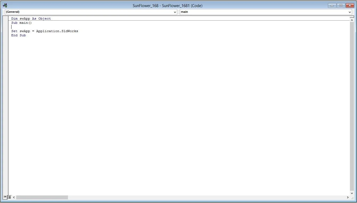
The programming window pops up. This is where we are going to write our small macro in visual basic (VBA). Type the code below while making sure to change the directory of Seed#168.txt with your own path.
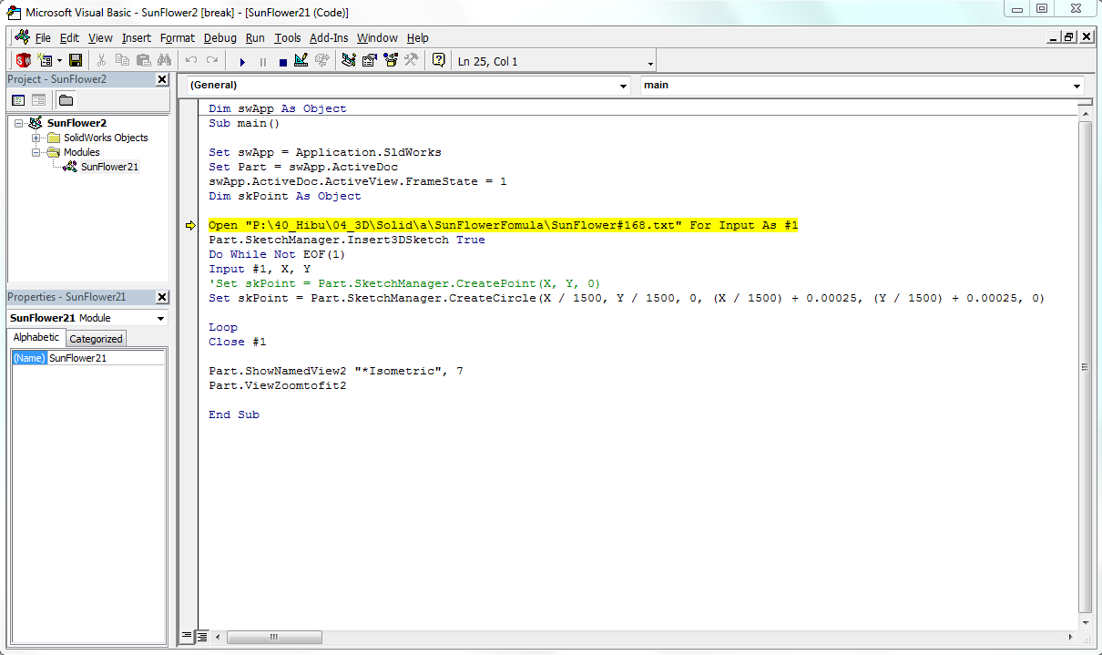
Sub main()
Set swApp = Application.SldWorks
Set Part = swApp.ActiveDoc
swApp.ActiveDoc.ActiveView.FrameState = 1
Dim skPoint As Object
Open "C:\Users\francois\Dropbox\seedcoordinate\Seed#168.txt" For Input As #1
Part.SketchManager.Insert3DSketch True
Do While Not EOF(1)
Input #1, X, Y
Set skPoint = Part.SketchManager.CreatePoint(X, Y, 0)
Loop
Close #1
Part.ShowNamedView2 "*Isometric",
Part.ViewZoomtofit2
End Sub
Step 4: Running the macro
We are now ready to run the macro:
Tool > Macro > Run
Select the macro we wrote. The points are imported as below in a sketch.
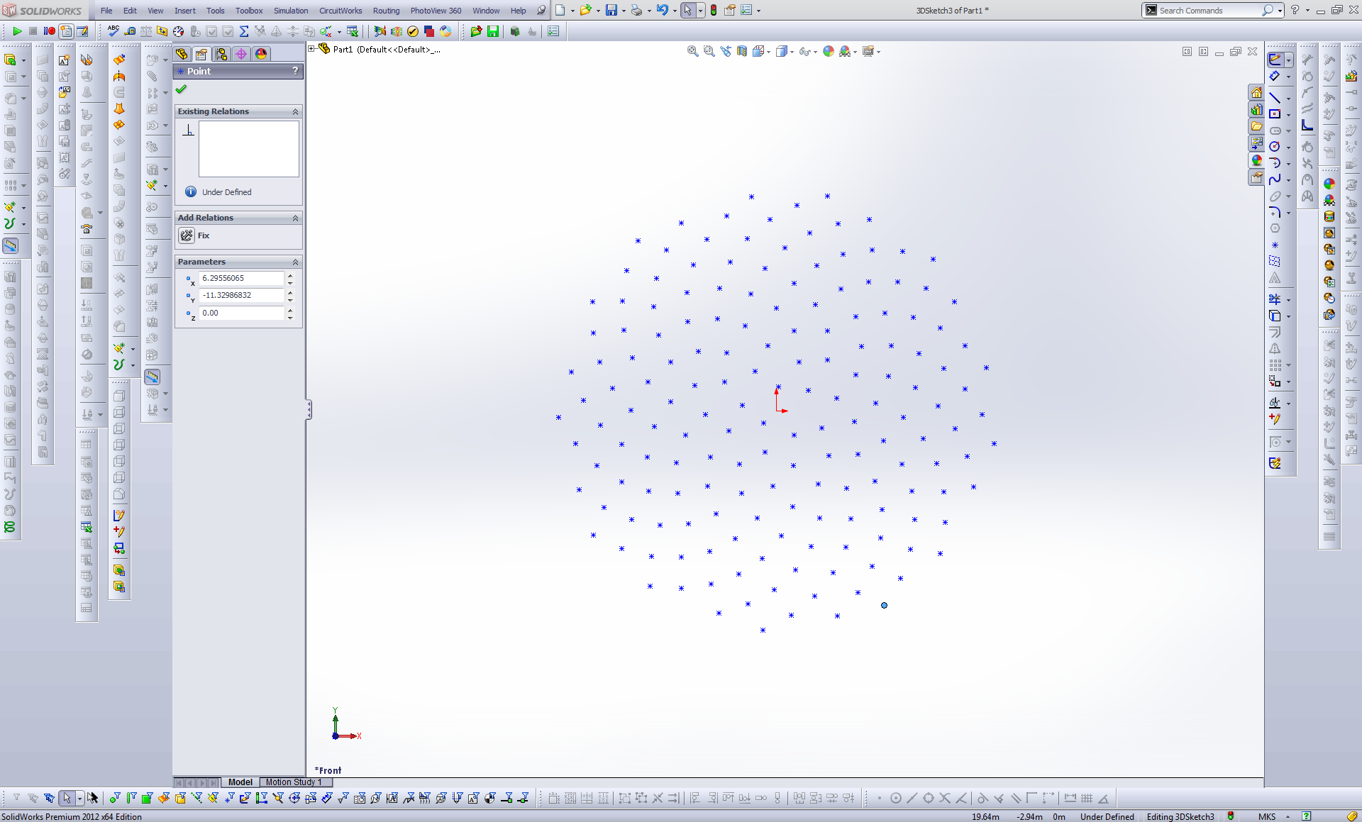
Scale matters here. The default unity in VBA is in meters and I end up by having a huge pattern. If we want to reduce the size of our pattern, we can modify the scale proportionally right in VBA:
Set skPoint = Part.SketchManager.CreatePoint(X, Y, 0)
changes for example to:
Set skPoint = Part.SketchManager.CreatePoint(X / 1500, Y /1500, 0)
Now that our points are placed properly on the sketch, we can go a little bit further by drawing a circle around each of the points.
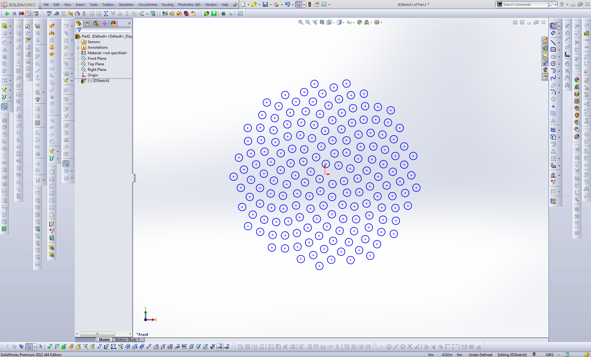
This is where writing your own macro is very powerful and time-saving. Instead of drawing manually each circle, we are just going to write a few more characters to our code:
Dim swApp As Object
Sub main()
Set swApp = Application.SldWorks
Set Part = swApp.ActiveDoc
swApp.ActiveDoc.ActiveView.FrameState = 1
Dim skPoint As Object
Open "C:\Users\francois\Dropbox\seedcoordinate\SunFlower#168.txt" For Input As #1
Part.SketchManager.Insert3DSketch True
Do While Not EOF(1)
Input #1, X, Y
Set skPoint = Part.SketchManager.CreateCircle(X / 1500, Y / 1500, 0, (X / 1500) + 0.00025, (Y / 1500) + 0.00025, 0)
Loop
Close #1
Part.ShowNamedView2 "*Isometric", 7
Part.ViewZoomtofit2
End Sub
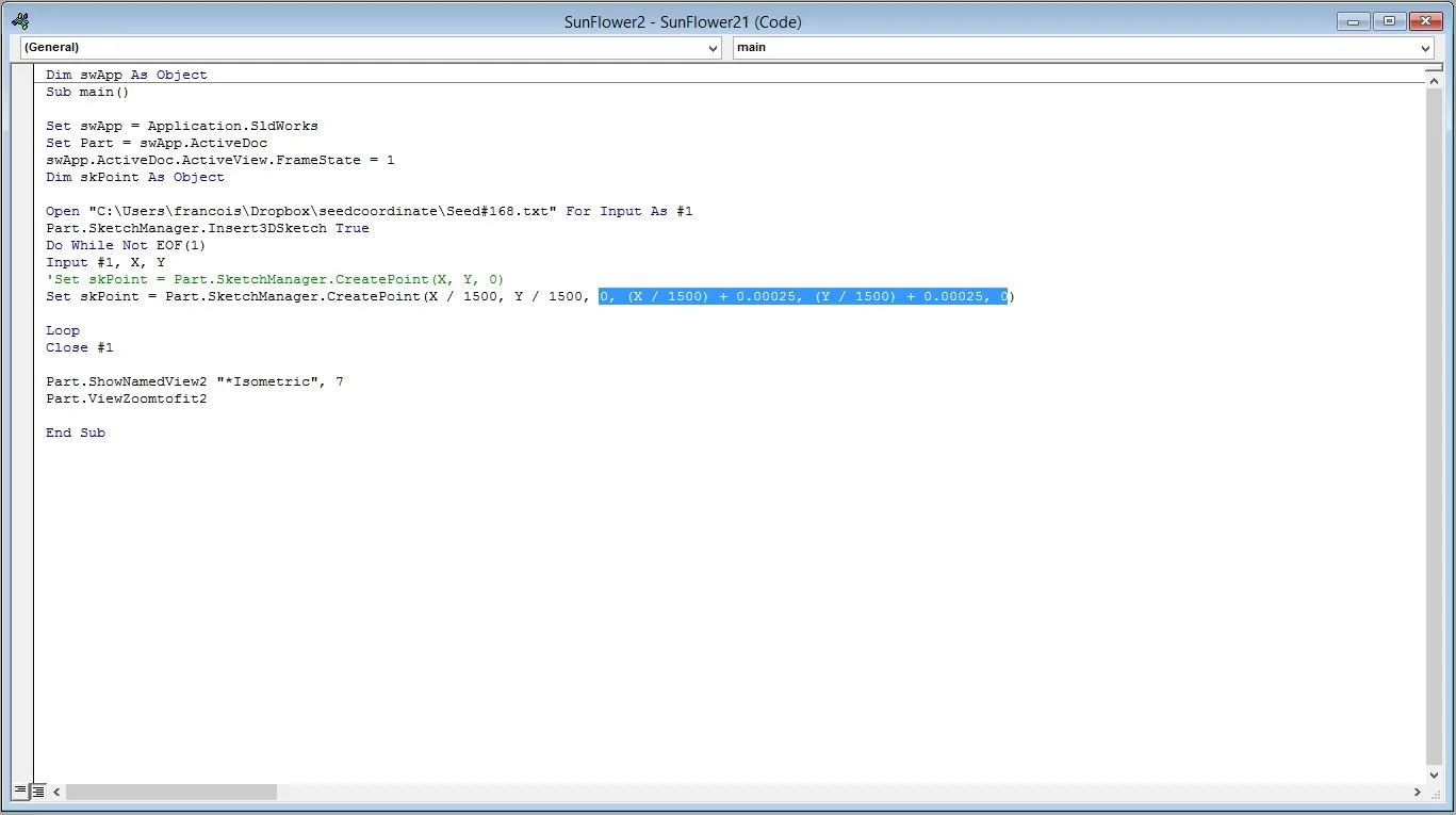
In the sketch above, we have change:
Set skPoint = Part.SketchManager.CreatePoint(X / 1500, Y /1500, 0)
to:
Set skPoint = Part.SketchManager.CreateCircle(X / 1500, Y / 1500, 0, (X / 1500) + 0.00025, (Y / 1500) + 0.00025, 0)
where we are adding the dimension of the ray of all the circles.
Important:
Check the directory of the .txt
Unity is in meters.
There is a wide array of pattern possibilities available from that source. I decided to incorporate a delicate tactile sensation for “Hibu”’s panic button, aiming to subtly enhance the user experience.

If you found this tutorial helpful, I would genuinely appreciate knowing what projects you have been working on lately. Don't hesitate to share your creations and ideas. Thank you for your support.